Designing a Holographic Grating Machine
I need a diffraction grating. Specifically, a 1200 lines/mm holographic grating on a glass substrate, for a Czerny-Turner spectrometer I’m building to characterize a ~485nm laser diode. The spectrometer is one step in a longer path toward an external-cavity diode laser for rubidium Rydberg atom electrometry – but that’s another story. The point is: I need gratings, I’ll need several of them (some will be bad), and buying them at $80-150 each adds up fast when you’re iterating.
So, I’m building a machine to make them.
The principle is simple: two coherent beams from the same laser source intersect at a controlled angle on a photoresist-coated glass slide. The interference pattern – a sinusoidal fringe field – exposes the resist. After chemical development, the resist washes away where it was exposed, leaving a surface-relief diffraction grating. The line density is set entirely by the intersection half-angle \(\theta\) and the wavelength \(\lambda\):
$$d = \frac{\lambda}{2 \sin\theta}$$
For 1200 lines/mm (\(d = 833\) nm) at 405 nm, the required half-angle is \(\theta = 14.06°\). The rest is just engineering.
The optical problem
The machine needs to take a single laser beam, split it in two, and recombine the halves at precisely \(\pm 14.06°\) on a microscope slide. The beams must be:
- Coherent: derived from the same source with matched path lengths, so the fringe pattern is stable
- Collimated: having planar wavefronts at the substrate, so the fringes are straight and uniform
- Clean: consisting of a single spatial mode, so the fringe contrast is high
A fiber-coupled 405-nm laser diode handles the source. I went with a single-mode fiber ($350, 3-µm core, 0.13 NA, 80-mW) rather than the cheaper multimode option ($130, 9-µm core, ~40 modes). The multimode fiber would need a pinhole spatial filter to select a single mode, and while the power budget is absurdly forgiving (I should only need ~0.15 mW at the substrate) the SM fiber eliminates an entire subsystem. The power will be controlled by driving the diode at reduced current, well above threshold but far below maximum.
A collimating lens turns the diverging fiber output into a ~9-mm parallel beam. The lens focal length matters: too long, and the diverging cone overfills the lens aperture, wasting most of the light (and contributing to stray reflections). The critical FL is \(f_{\max} = d_{\text{lens}} / (2 \cdot \text{NA})\), where the cone exactly fills the lens. Above this, and you’ll start clipping the cone. I’m using \(f = 35\) mm with a 12.7-mm lens, which should provide full capture.
Three designs
v1: Beamsplitter cube with axis-aligned mirrors
The first design was the obvious one. A non-polarizing beamsplitter cube splits the collimated beam into transmitted (+x) and reflected (+y) paths. Two flat mirrors at a fixed distance redirect both beams to converge on the substrate.
It works geometrically. The convergence distance is reasonable (~50 mm from the BS) and the beam overlap is fine. But the mechanical layout is awkward – the two beam paths have different lengths. Path-length mismatch degrades fringe visibility because the laser’s coherence length, while long, isn’t infinite. It’s possible that this wouldn’t have been an issue, but I decided to fix it anyway, just in case.
I built a full OpenSCAD model and a Python ray-trace diagram, but the asymmetry bothered me.
v2: Symmetric chamfer layout
The second attempt tried to fix the symmetry problem by redirecting both beams toward a 45° chamfered corner. I explored an input-from-below orientation. The geometry calculations checked out, but the mechanical complexity increased without solving the fundamental problem. This design never got past a Python script. A dead end.
v3: Diamond beamsplitter with steering mirror
The third design is the first one I’m going to build.
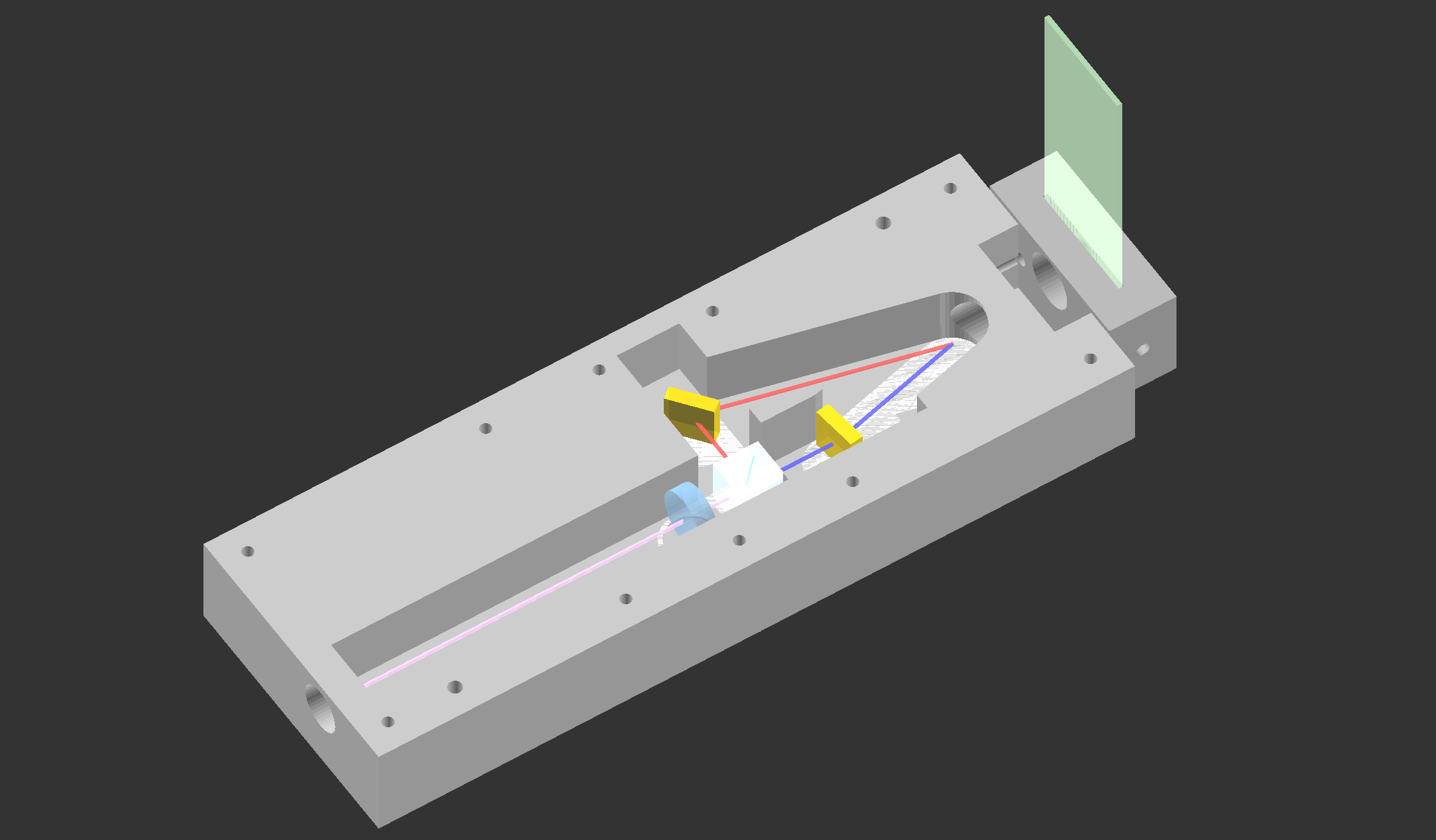
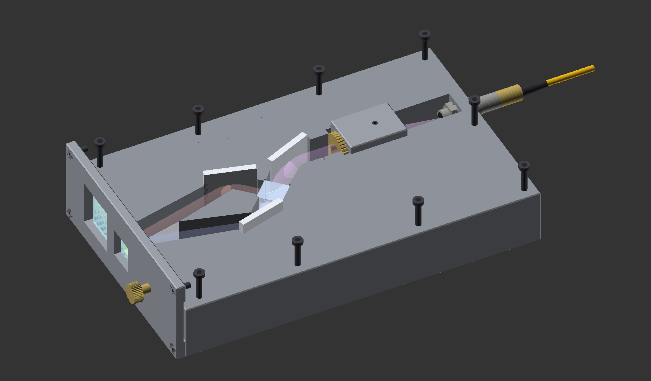
The input beam enters from the south face of the housing, passes through a collimating assembly, and hits a steering mirror that redirects it northwest into a beamsplitter cube oriented in diamond configuration (rotated 45°). The transmitted beam exits northwest; the reflected beam exits northeast. Two redirecting mirrors (M1, M2) steer both beams to converge symmetrically at the substrate on the north face.
The key insight: the layout is symmetric, so up to machine tolerances, the path-length mismatch is zero. Both beams travel the same distance from the BS to the substrate, through geometrically identical paths.
The mechanical design
The housing is a 3-part aluminum construction designed for a Haas TM1:
Base billet: all the optics live in channels milled from the top. Mirror pockets machined at the correct angles, a BS cube pocket in diamond orientation with a shelf for seating, a rectangular pocket for the lens staging mechanism, and a fiber port on the south face. The channels are 14 mm wide (beam is ~9 mm plus margin) and 14 mm deep.
Lid: a flat plate that bolts on top, sealing the channels.
Slide cap: bolts to the north face. A slit on the west side lets you slide a microscope slide in. An M5 thumbscrew clamps it against the north face. An exposure window behind the beam convergence point prevents back-reflections from re-exposing the resist. A square finger hole lets you push the slide back out.
Why fixed mirrors
The mirrors are epoxied into machined pockets at fixed angles. No adjustable kinematic mounts, and no fine-pitched screws. This is by design.
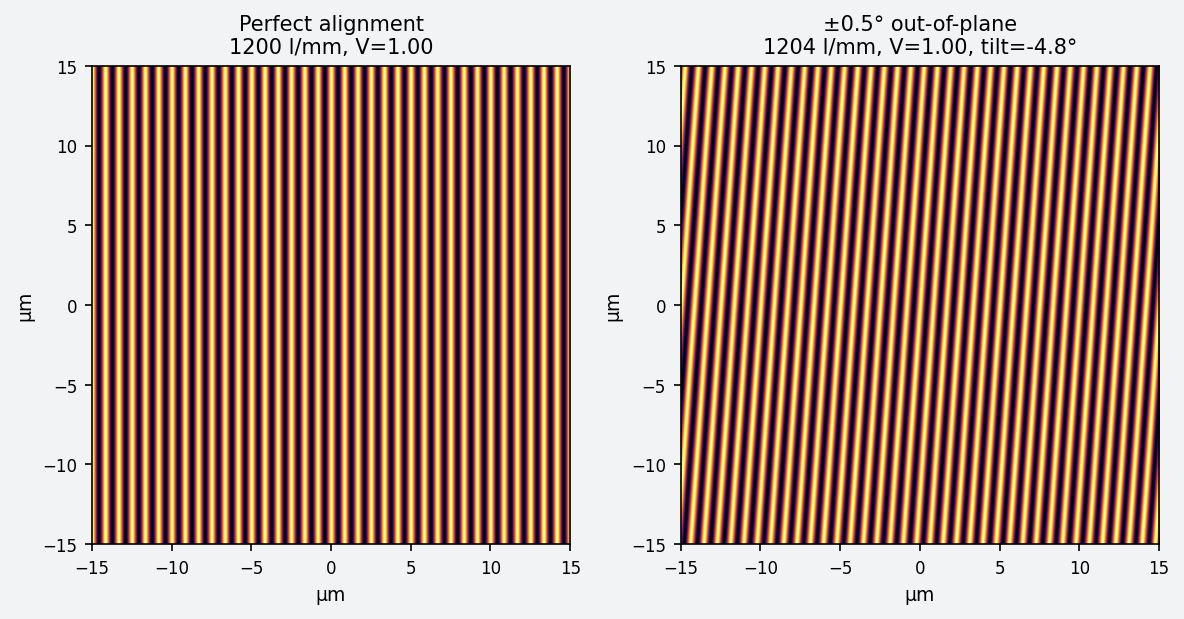
The TM1’s endmill sidewall finish gives pocket floor flatness of ~\(\pm 0.02°\) (\(\pm 1\) arcmin). A sensitivity analysis shows that \(\pm 1\) arcmin on the mirrors gives \(\pm 1.7\) lines/mm error in line density and ~3.6 fringes of tilt across the beam. Both are acceptable: the line density will be calibrated against discharge lamp spectra anyway, and a few fringes of tilt just means the grating area is slightly smaller than the beam diameter.
Once the geometry is right, there is nothing to drift. The machine can sit on the shelf for a year, and the next grating will be identical (ish) to the last one (modulo environmental conditions etc).
Focus staging
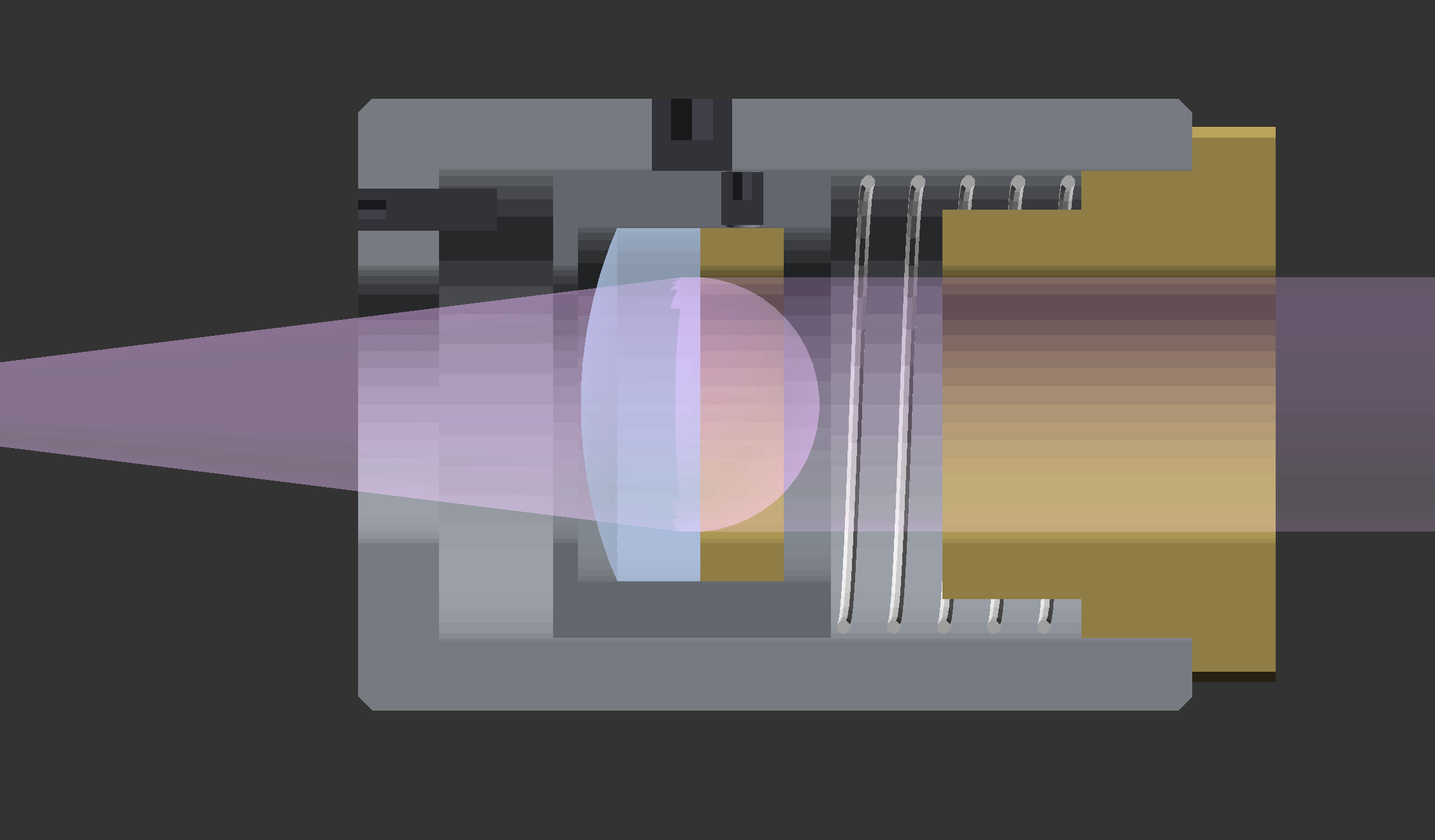
The collimating lens needs to sit at exactly one focal length from the fiber tip, but cheap lenses have \(\pm 1\text{-}2\) mm FL tolerance. A fixed pocket won’t work.
The solution is a sliding lens cell in a cylindrical bore, driven by a fine-pitch M3x0.5 push screw with a compression spring return. The spring eliminates backlash – the cell is always pushed south against the screw tip. Fine pitch gives ~14 µm of travel per degree of screw rotation, which is more than adequate for finding the collimation point.
The adjustment procedure: remove the lid, insert a ball-end hex key through the south channel, turn the push screw while projecting the beam onto a distant wall. When the spot size is constant at all distances, you’re collimated. Tighten the radial set screw to lock the cell. Replace the lid. This should only need to be done once.
The entire staging mechanism is a self-contained subassembly that drops into a pocket in the base.
Stray light
Bare aluminum is ~90% reflective at 405 nm. Every surface inside the housing is a potential source of incoherent background light that washes out fringe contrast. The main sources are probably Fresnel reflections off the BS faces (~4% per surface), beam overfill past mirror edges, and back-reflections from the substrate.
The exposure window in the cap helps to reduce back-reflection. For the rest: black anodization (type II sulfuric, dyed black) drops reflectivity to ~5-15%. If trouble spots remain after testing, black flocking sheet is the backup. The plan is to build it anodized and add flocking only where needed.
The shutter problem
Exposure timing matters. At full laser power, the photoresist dose would accumulate in under a second – too fast for manual control. At reduced drive current (1-5 mW coherent output), exposures land in the 20-100 second range, which is comfortable.
But you still need a shutter. I considered a separate shutter block in the fiber path, but that means breaking and re-mating a single-mode fiber coupling, which is a pain and risks alignment loss.
The solution: a 1.5-mm slot cut through both the lid and base, over the north collimator channel between the staging housing and the steering mirror. A piece of black cardstock drops into the slot and seats against solid aluminum on all sides for a total light seal. Pull the card out to begin exposure. Drop it back in to stop. Nearly zero vibration, no optical penalty, and no mechanism to maintain.
What’s next
The v3 design is complete and ready for machining. Bill of materials is ~$660-720, with the laser accounting for half. The photoresist process (Shipley S1800 series, 50-100 mJ/cm² dose at 405nm) is well-documented and straightforward. Another project in the pipeline before actually making a grating is the design and construction of a DIY spincoater.
After the first gratings are made and characterized in the spectrometer, the next step is vacuum-depositing ~100-150 nm of aluminum on top of the developed resist pattern to create a reflective grating. I’m planning to build a small thermal evaporator (bell jar + roughing pump + tungsten filament) for this – a tool that will be useful for the broader ECDL project as well (not to mention a plethora of other future ideas).
The source code and CAD files are on GitHub.